 NEW JOURNEY
UAV Battery Procurement and Selection Guide
Screen UAV battery configurations by mission voltage, output and pack mass. Compare six cells, installation, charging turnaround and purchasing acceptance, with a mass-screening example and editable project templates.
NEW JOURNEY · Xiamen New Journey Technology Co., Ltd. · 2026-10-25
On this page
1 UAV battery procurement process
2 Technology routes and product forms
3 Reading battery specifications
4 Application requirements
5 Cell comparison
6 Screening case From electrical limits to mass and validation
7 Battery pack customization
8 Battery bay, swelling and temperature
9 Charging schedule and spare batteries
10 Sample testing and acceptance
11 Cost per completed mission
12 Delivery documents and revision control
13 New Journey customization support
14 RFQ inputs and purchasing checklist
Appendix Terms and references
1 UAV battery procurement process
A UAV battery purchase concerns an electrical system that must perform a defined mission repeatedly. Capacity, energy density, rate and price are starting points. The decision must establish whether the system can supply the required power, fit the aircraft, support the schedule and remain consistent in repeat orders under the intended payload, weather and reserve policy.
This guide is for UAV manufacturers, system integrators and professional operators. Eliminate configurations that fail mission, voltage or mass limits, then compare cell energy, output, installation and turnaround. Use the result to prepare a sample plan and a purchasing specification. Chapter 6 is an illustrative screening case; its aircraft, mission, mass limit, cost and derating inputs are assumptions.
| Stage | Required result | Evidence |
|---|---|---|
| Define the mission | Payload, phases, environment and sorties | Logs or justified power budget |
| Check hard constraints | Voltage, current, space and mass limits | Aircraft and charger documentation |
| Screen products | Retain, reject or hold each option | Matching revisions and conditions |
| Specify a sample | Configuration, interfaces and protection | Agreed drawing and specification |
| Validate the mission | Bench, aircraft and pilot conclusions | Criteria agreed before testing |
| Purchase and reorder | Controlled supply, acceptance and service | Order technical annex and records |
Keep three decisions separate: reject because a hard constraint fails; hold because evidence is missing; or shortlist for sample validation. Missing evidence is not a pass. Strong price or density scores cannot compensate for incompatible voltage, discharge duty or installation.
2 Technology routes and product forms
Separate three dimensions when reading high-energy, semi-solid, anode-free and pouch claims. Form describes packaging; electrode architecture describes energy storage; electrolyte and separator design describe ion transport and separation. A single label does not establish all three, or prove endurance, power, life or safety.
| Dimension | Purchasing relevance | Evidence to request |
|---|---|---|
| Pouch, cylindrical and other forms | Affects mounting, cooling, connections and packaging; form alone does not determine rate | Dimensions by state, mass, terminals and installation |
| Electrode materials and architecture | Anode-free generally describes the manufactured initial state, not the absence of an operating anode | Chemistry, operating window, life conditions and maturity |
| Liquid, hybrid and solid-state descriptions | Identify which components are solid | Manufacturer definition, exact-model specification and tests |
QuantumScape describes an anode formed during initial charging, with a solid separator and organic liquid catholyte. This clarifies terminology, not Golden Feather construction. Molicel’s cylindrical P45B specifies 45 A continuous discharge with an 80°C cutoff, disproving the assumption that cylindrical means low power. That cutoff is not a recommended UAV operating temperature. [R1][R2]
Choose between energy, output and turnaround
Endurance emphasizes usable energy and aircraft mass. Heavy climbing, repeated take-off and aggressive manoeuvring emphasize loaded voltage, sustained current and heat. High utilization also depends on charging, cooling and spare packs. Optimize operating results after meeting the mission, rather than maximizing one number.
Research, engineering, customer-validation and production samples support different evidence. Ask about supply maturity, sample-to-production differences, expected changes and available records. A technical development does not automatically qualify a battery for an aircraft.
3 Reading battery specifications
Capacity, energy and power answer different questions
Ah expresses charge capacity, Wh energy and W instantaneous power. Nominal voltage times rated Ah gives nominal Wh. Usable energy comes from discharge data under defined cutoffs, temperature, current and ageing. Comparing Ah across voltages is misleading. A typical capacity must not replace a rated or minimum contractual value.
Use the datasheet capacity basis for C-rate conversion. For 20 Ah, 3C is 60 A. This does not establish duration, temperature, cutoff or the pack limit. Pulses need duration, interval and thermal state. A two-minute take-off cannot use a ten-second peak rating.
| Parameter | Read alongside it | Purchasing effect |
|---|---|---|
| Voltage | Nominal, full, loaded minimum, cutoff and series count | Equal series counts may need different chargers |
| Capacity/energy | Rated/minimum/typical, temperature, current and cutoff | Defines reserve and acceptance |
| Current | Duration, temperature, SOC, cooling and repetition | Checks every flight phase |
| Charge rate | Temperature, CC/CV, termination and pack limit | Turnaround exceeds reciprocal C-rate |
| Resistance | AC/DC method, frequency/pulse, SOC and temperature | Unlike methods cannot be ranked |
| Life and ageing | Retention, rates, DoD, temperature and storage | Lab cycles are not sorties |
| Dimensions/mass | Tolerance, SOC, ageing, leads and connectors | Checks lasting installation |
Separate cell density from pack metrics
Cell density is a legitimate priority. Cell-specific energy uses cell-level Wh and kg; volumetric density uses cell-level Wh and litres, with capacity, voltage, mass, volume and state defined. Leads, connectors, wrap, supports and protection affect pack mass and envelope. Pack appearance cannot establish or discredit original cell density.
Keep the supplier’s cell specific-energy declaration, comparisons calculated from the same cell specification, and pack installation data in separate fields. If only a series range is supplied, request the proposed model and revision with its measurement conditions. Use the matching test report or approved specification to agree the supplied rating. Pack mass and installation dimensions serve aircraft integration and do not replace cell ratings.
4 Application requirements
| Application | Investigate first | Often missed | Priority |
|---|---|---|---|
| Mapping/inspection | Cruise, headwind return and dwell | Payload changes invalidate budget | Usable Wh, mass, return voltage |
| FPV/dynamic flight | Acceleration, climb and peaks | Repeated-pulse heat accumulation | Sag, pulses, connections |
| Agricultural spraying | Loaded take-off and changing load | Channels, site power and cooling | Current and turnaround |
| Heavy lift/logistics | Hover, climb and adverse return | Peak duration exceeded | Sustained current and heat |
| VTOL fixed-wing | Lift, transition and cruise | Cruise hides lift bottleneck | Both power and energy |
| Cold/intensive use | Temperature limits and daily schedule | Discharge range is not charge range | Temperature, charging and cost |
Application names identify questions, not compatibility. Spraying reduces payload; logistics outbound and return loads differ. Obtain phased logs covering the heaviest payload, adverse return and temperature boundaries. State whether sampling can capture peaks.
Without flight data, aircraft-side motor, propeller, controller and payload estimates can support screening. Replace them with measurements during sampling. Label estimates so an endurance target does not become a verified supplier promise.
Long-endurance inspection and mapping
Inspection buyers often trade a longer route against sensor payload. Fix the payload and take-off mass limit before comparing usable Wh and voltage late in the return leg. Higher cell specific energy can free a mass budget for energy or payload, while take-off, headwind return and late-mission loads must still be supported. Do not add these benefits together without aircraft validation.
AEP49Ah and ECP39Ah are two directions to discuss. AEP49Ah offers an energy/mass comparison but its 1C maximum discharge and 0.2C charge limit load and turnaround. ECP39Ah uses a 4.20 V charging platform and a 5C maximum discharge rating for a different screening path. Calculate current, total mass and full-charge voltage for the proposed S/P configuration before sampling. Change the configuration if a two-minute demand exceeds its allowed current or return-leg voltage is insufficient.
Agricultural spraying and repeated sorties
Agricultural purchasing should focus on completed daily work. Check current and sag at fully loaded take-off, then use phase-specific power records as spraying reduces mass. Cooling, charging and swapping determine the next departure. FAP22Ah and FAP30Ah are candidates for a charging/output discussion and both use a 4.35 V charge ceiling. Greater capacity changes mass and installation space, so choosing the larger Ah figure alone is insufficient.
First exclude an incompatible charging platform, a thermal condition that prevents the required charge rate, or inadequate site power. Then compare spare-pack and charging-channel combinations. The 5C maximum charge rating is not an instruction for every temperature or a promise of a 12-minute full charge. Chapter 9 separates inventory from throughput; the actual SOC window and shared charger power will change the result.
Heavy-lift logistics and VTOL fixed-wing aircraft
Heavy-lift logistics combines an extended high-power stage with a battery mass limit. VTOL fixed-wing aircraft combine cruise energy demand with take-off, transition and go-around output. List current, duration and repetition for each phase, especially a go-around at low SOC. A low cruise average must not hide a take-off or landing constraint.
ECP39Ah, FAP models and PCP45Ah can enter discussions under different voltage, capacity and charging requirements, each with a defined configuration. A 10- or 60-second pulse cannot cover a longer hover. Twelve PCP45Ah cells alone weigh about 9.168 kg; a project with a 7 kg pack budget should reject that 12S1P configuration at the RFQ stage. Application labels guide evaluation; the shortlist must meet the aircraft’s mass, voltage, thermal and mission-load limits.
5 Cell comparison
These six models span energy-oriented, fast-charge/output and alternative-capacity platforms. Values are cell declarations from cited revisions, not pack or aircraft qualifications. The table does not rank prices.
| Model / source | Rated Ah / nominal V | Charge limit V | Max charge / discharge | Peak |
|---|---|---|---|---|
| AEP8390192-49Ah [S1] | 49 / 3.8 | 4.30 | 0.2C / 1C | Not set here |
| FAP10790192-22Ah [S2] | 22 / 3.75 | 4.35 | 5C / 10C | 20C 10 s |
| FAP105105230-30Ah [S3] | 30 / 3.75 | 4.35 | 5C / 10C | 20C 10 s |
| ECP11087188-39Ah [S4] | 39 / 3.6 | 4.20 | 1C / 5C | 7C 10 s |
| PCP10090192-20Ah [S5] | 20 / 3.7 | 4.30 | 2C / 3C | 5C 60 s |
| PCP104136260-45Ah [S6] | 45 / 3.7 | 4.30 | 1C / 2C | 5C 10 s |
Apply temperature conditions. AEP49Ah permits maximum 1C discharge at 0–45°C and no more than 0.3C at −20 to 0°C. FAP30Ah’s −10°C charging test uses 1C, not its maximum 5C. PCP20Ah and 45Ah specify 0.1C charging at −15°C. [S1][S3][S5][S6]
Align life-test conditions
ECP39Ah lists 300 cycles at 1C charge/3C discharge and 600 at 0.5C/0.5C, both to at least 80% capacity. FAP30Ah’s 1,000 cycles use 5C/10C at 25±3°C with defined cutoffs and rests; PCP20Ah uses 1C/1C. Counts alone cannot rank these or establish equal flight sorties. [S3][S4][S5]
Resolve version conflicts. EBP110105230-50Ah A3 specifies a 4.20 V charging cutoff while a differently dated catalogue gives 4.25 V. Do not select the higher value or borrow from a similar model. Confirm delivery revision, charger settings and corrected documentation in the order. [S7]
Read energy, mass and mission limits together
| Model | Nominal Wh | Cell mass g | Initial trade-off |
|---|---|---|---|
| AEP49Ah | 186.2 | 390±5 | Energy/mass merit comparison; 1C and charge turnaround constrain duty |
| FAP22Ah | 82.5 | 411±5 | Output/fast-charge candidate requiring a 4.35 V platform |
| FAP30Ah | 112.5 | 559±5 | More capacity than 22 Ah, with more mass and different fit |
| ECP39Ah | 140.4 | 430±5 | 4.20 V platform; check pack current and mission life |
| PCP20Ah | 74.0 | 354±5 | Smaller capacity; match 3C maximum discharge and 60 s peak duty |
| PCP45Ah | 166.5 | 764±5 | Higher capacity with mass and 2C limits to evaluate |
The table uses rated Ah times nominal voltage for nominal Wh and the mass from the same cell specification. The next table gives a cell-level specific-energy comparison to support cell mass budgeting. This differs from measured Wh/kg obtained by integrating a defined discharge curve.
Comparing cell specific energy
| Cell and specification revision | Supplier model-specific density declaration | Nominal Wh / nominal kg comparison |
|---|---|---|
| AEP49Ah · A2 [S1] | No separate Wh/kg rating in cited specification | 186.2 / 0.390 ≈ 477.4 Wh/kg |
| FAP22Ah · A0 [S2] | No separate Wh/kg rating in cited specification | 82.5 / 0.411 ≈ 200.7 Wh/kg |
| FAP30Ah · A1 [S3] | No separate Wh/kg rating in cited specification | 112.5 / 0.559 ≈ 201.3 Wh/kg |
| ECP39Ah · A2 [S4] | No separate Wh/kg rating in cited specification | 140.4 / 0.430 ≈ 326.5 Wh/kg |
| PCP20Ah · A0 [S5] | No separate Wh/kg rating in cited specification | 74.0 / 0.354 ≈ 209.0 Wh/kg |
| PCP45Ah · A1 [S6] | No separate Wh/kg rating in cited specification | 166.5 / 0.764 ≈ 217.9 Wh/kg |
The comparisons use nominal cell masses, each with a ±5 g tolerance. They include no external wiring, pack packaging or pack dimensions and are not supplier-guaranteed minimum specific-energy ratings. Use them for screening, not to predict usable energy at high current, low temperature or end of life. Agree the cell revision, energy-test current and temperature, voltage limits, cell mass and acceptance method for a purchased specific-energy guarantee. Confirm Wh/L separately using cell body volume in an agreed state.
The catalogue dated 25 September 2025 separately describes the Wuji series as 450–550 Wh/kg, the agricultural series as approximately 210 Wh/kg, and ECP models under the “340 series.” These remain supplier series descriptions. Model-specific purchasing uses the matching approved specification; series descriptions and the nominal calculations above serve different purposes. [S9]
Screen current ratings with their temperature conditions
| Model | Charge / discharge operating temperatures | Screening condition |
|---|---|---|
| AEP49Ah [S1] | 0–45°C / −20–45°C | 1C maximum discharge at 0–45°C; at −20–0°C, at most 0.3C |
| FAP22Ah [S2] | −20–60°C / −40–60°C | 5C maximum charge, 10C maximum discharge; 20C for 10 seconds only. Confirm rate by temperature |
| FAP30Ah [S3] | −10–60°C / −20–60°C | 5C / 10C are specification maxima; −10°C charge test uses 1C; 20C for 10 seconds only |
| ECP39Ah [S4] | 0–45°C / −20–55°C | 1C / 5C are specification maxima; 7C for 10 seconds only; full rate across the range is not established |
| PCP20Ah [S5] | −15–60°C / −20–60°C | 2C / 3C are specification maxima; 5C for 60 seconds; −15°C charge test uses 0.1C |
| PCP45Ah [S6] | −15–60°C / −20–60°C | 1C / 2C are specification maxima; 5C for 10 seconds; −15°C charge test uses 0.1C |
“Maximum discharge” follows the specification wording. It does not establish unrestricted pack operation at every SOC, temperature or cooling condition. Obtain discharge curves and thermal conditions for a two-minute climb or repeated pulses, then validate the pack. The AEP49Ah discharge-performance clause specifies more than 80% capacity retention after 20 cycles at 0.3C, 25±3°C and 0 MPa. Agree service-life requirements against the actual mission duty. [S1–S6]
Turn a cell shortlist into a custom RFQ
| Candidate direction | Mission discussion | Include in the RFQ |
|---|---|---|
| AEP49Ah / ECP39Ah | Endurance under a mass limit | Mission load, mass limit, reserve rule, temperature and charging schedule |
| FAP22Ah / FAP30Ah | Charging turnaround and higher output | 4.35 V platform compatibility, loaded take-off curve, site power and spares |
| PCP20Ah / PCP45Ah | Capacity, installation and temperature requirements | Current at the specified temperature, mass/space, peak duration and life target |
These are custom-evaluation paths, not automatic substitutions for catalogue packs. Send New Journey the full cell model, specification revision and mission brief to confirm availability, proposed S/P configuration and sample scope. Add a finished-pack model and its relevant documents to the quotation once the configuration mapping is established.
6 Screening case From electrical limits to mass and validation
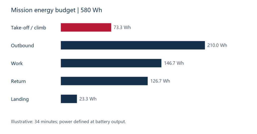
This hypothetical 34-minute inspection mission demonstrates the method, not a delivered aircraft. Assume a 36–52 V electrical window. Power is measured at the battery output, so motor/controller efficiency must not be deducted again. Payload and flight method are fixed for this budget.
| Phase | Time min | Battery power W | Energy Wh |
|---|---|---|---|
| Take-off / climb | 2 | 2200 | 73.3 |
| Outbound | 14 | 900 | 210.0 |
| Work | 8 | 1100 | 146.7 |
| Return | 8 | 950 | 126.7 |
| Landing | 2 | 700 | 23.3 |
| Total | 34 | Phase-dependent | 580.0 |
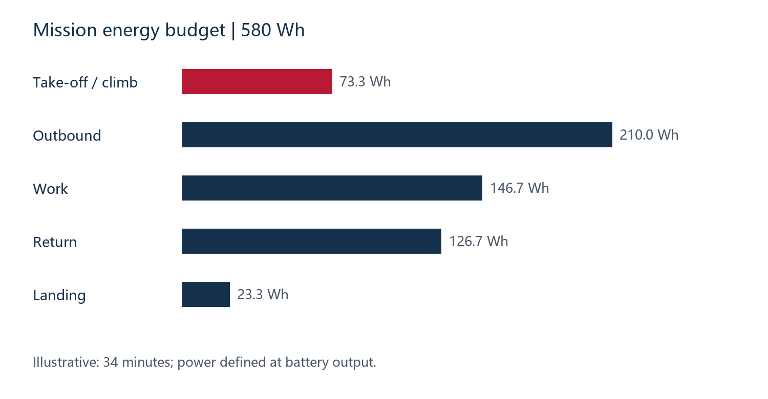
Step 1 Calculate required nominal energy
Phase energy equals power × minutes ÷ 60. Assume 15% is withheld from normal mission use, an ageing capacity factor of 0.90 and a combined temperature/rate factor of 0.95. Required nominal energy is 580 ÷ (0.85 × 0.90 × 0.95) = 798.1 Wh. Replace these assumptions with operational rules and measurements. Do not deduct losses already included in measured energy.
For an abstract comparison, 12S at 3.6 V nominal per cell and 20 Ah gives 864 Wh; 16 Ah gives 691.2 Wh. The latter fails; the former passes only the energy screen. Added capacity may increase aircraft mass and power, so added Wh do not necessarily produce proportional endurance.
Step 2 Check voltage and sustained current
At 12S, 4.20 V per cell gives 50.4 V full charge, within the assumed ceiling. At 4.35 V, 52.2 V exceeds it. A revised charging limit needs manufacturer-supported capacity, balancing and charging validation; original full-charge energy cannot simply be retained.
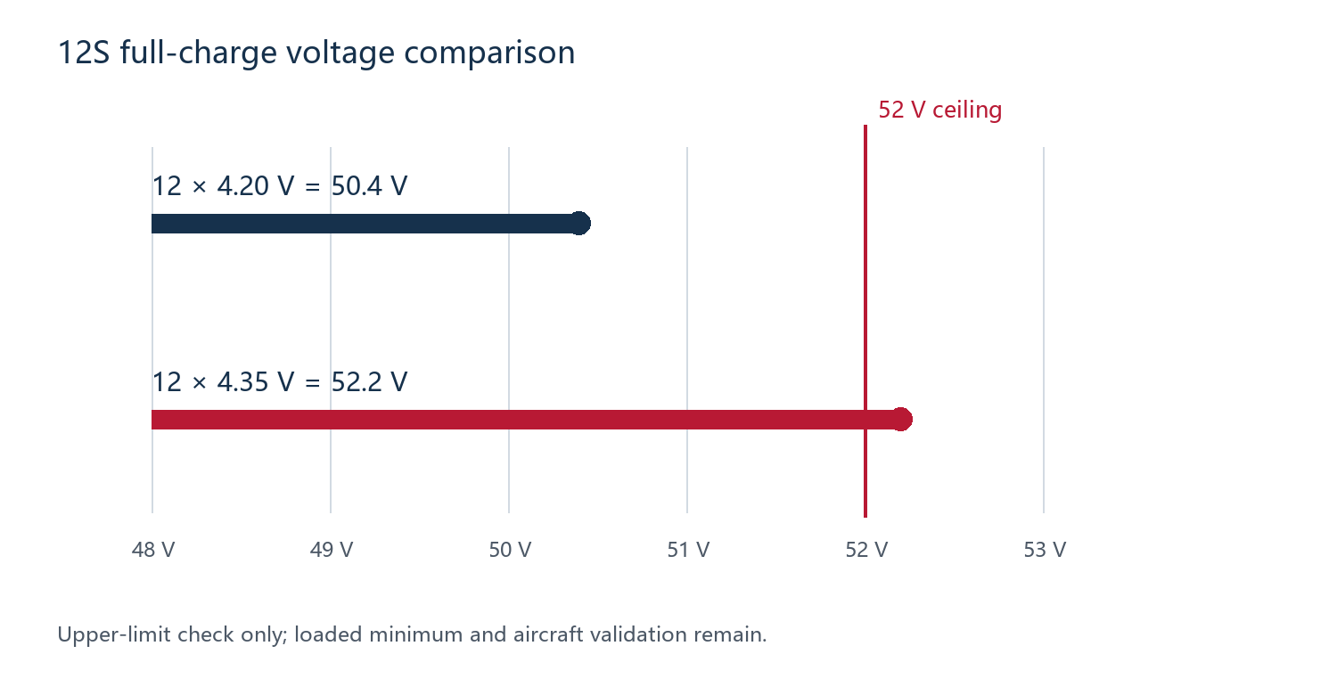
At 36 V, take-off requires 2200 W ÷ 36 V = 61.1 A. For 20 Ah, 1P, this is about 3.06C for two minutes. A candidate with a 3C/60 A maximum discharge rating does not pass because the values are close. A ten-second peak cannot cover two minutes. Revise the candidate, configuration or mission, then verify sag and heating.
Step 3 Retain configurations for mass and installation review
The 16Ah energy example and the 52.2 V configuration without a system redesign are excluded first. Remaining options must satisfy the two-minute 61.1 A demand, return-leg voltage, mass, fit and thermal limits. Check both remaining energy and loaded voltage: unused Ah will not prevent an interruption if voltage sag triggers protection.
Retain assumptions, calculations, rejection reasons, open tests and data owners. Revisit the power budget when payload, propeller, flight method or battery mass changes rather than editing only the capacity entry.
Apply the example constraints to actual candidates
| Illustrative 12S1P candidate | First screening result | Decision |
|---|---|---|
| AEP49Ah | 51.6 V full; 1C = 49 A, below 61.1 A for two minutes | Reject this configuration; more energy cannot fix current |
| FAP22Ah / FAP30Ah | 52.2 V full exceeds the 52 V system ceiling | Reject original charging configuration; redesign needs validation |
| PCP20Ah | 51.6 V full; 3C = 60 A, below 61.1 A | 5C for 60 s cannot cover two minutes |
| ECP39Ah | 50.4 V full; cell 5C = 195 A exceeds 61.1 A | Retain provisionally; verify pack limits, mass, temperature and fit |
| PCP45Ah | 51.6 V full; cell 2C = 90 A exceeds 61.1 A | Retain provisionally; reassess energy, mass and operating value |
These are the stated voltage/current screens under an assumed room-temperature condition, not aircraft qualification. The two retained models differ in capacity, mass and operating window. Feed actual pack mass back into the mission model and check loaded voltage, heat and charging. Other capacities or configurations may also merit investigation.
Step 4 Eliminate configurations above the pack mass limit
Add an explicit assumption: the aircraft allows a complete installed pack mass of 7.00 kg, including cells, interconnects, insulation, harness, protection and restraints. Twelve ECP39Ah cells have a nominal combined mass of 12 × 0.430 = 5.160 kg; twelve PCP45Ah cells total 12 × 0.764 = 9.168 kg. These are cell-mass sums, not measured pack masses or a conversion of cell density.
| 12S1P configuration | Cell mass including ±5 g per cell | Decision against the 7 kg pack budget |
|---|---|---|
| ECP39Ah | 5.100–5.220 kg | At the upper cell mass, at most 1.780 kg remains for other parts; continue design and weighing |
| PCP45Ah | 9.108–9.228 kg | Even the lower cell mass exceeds 7 kg; reject this configuration |
The ECP option’s 1.780 kg allowance is a budget, not proof that the remaining components fit it. List structural, connection and electronic masses, then weigh the assembled sample. Recalculate after changes to parallel count, enclosure or protection. PCP45Ah is rejected for this example’s 7 kg limit, not for aircraft with a larger mass allowance.
Step 5 Complete drawing and late-mission load checks
Start installation review with the customer’s bay drawing, rather than multiplying cell dimensions alone. ECP39Ah specifies an initial thickness limit of 11 mm measured with a 2000 gf PPG, and a 13.2 mm limit after the cycles in specification section 6.1.2, a width limit of 88 mm and a length limit of 189 mm. Use the relevant state in the pack drawing and add insulation, connections, structure, lead exits and connector service space. [S4] No bay geometry is assumed in this example, so fit remains a drawing-review requirement.
A 12S1P ECP39Ah configuration has 12 × 3.6 × 39 = 1684.8 Wh nominal energy. Applying the illustrative factors gives a 1224.4 Wh budgeted usable value, above the 580 Wh mission estimate. This only means energy is not the first exclusion under those assumptions; it is not a 34-minute flight guarantee. The power profile must match actual payload and pack mass. After weighing the sample, obtain phase power for that aircraft, payload and mission, then recalculate energy and reserve.
| Final check | Sample record | Decision |
|---|---|---|
| Energy and late mission | Wh, pack voltage and minimum cell voltage under the updated load profile, including late return/go-around | Retain the agreed reserve; 36 V is this example’s lower system limit, not a normal operating target |
| Two-minute load | Replay the mission power and temperature associated with at least 61.1 A demand; record thermal state and protection | Validate cell and pack conditions, not just the 5C number |
| Mass and installation | Measured total mass, dimensions/state, restraints, lead routing, connector access and checks after vibration | Proceed to aircraft trials only with ≤7 kg complete mass and approved fit |
| Purchase decision | Sample revision, anomaly resolution, test conclusion and technical order annex | Discuss a pilot order after passing; otherwise change configuration, mission or aircraft |
This example retains ECP39Ah 12S1P for engineering-sample evaluation, excludes PCP45Ah 12S1P on mass and excludes the other candidates on the stated electrical constraints. The next purchasing step is to agree the pack drawing, component mass budget and mission test plan before a production order.
7 Battery pack customization
Cell current capability is not pack capability. Interconnects, welds, protection, fuses, connectors, cables and cooling constrain output. Parallel arrangements require current-sharing, symmetry and consistency checks. A cell C-rate calculation alone is not a pack guarantee.
The 86.4 V, 39 Ah, 24S1P pack specification lists 117 A continuous, 195 A for three minutes and a 100.8 V charge cutoff. [S8] Use those pack limits. A separate 39 Ah cell’s 5C entry cannot rewrite this pack’s continuous limit without verified cell/configuration mapping.
| Interface | Agreement required | Problem addressed |
|---|---|---|
| Electrical/charging | Configuration, cutoffs, duty, settings, polarity and keying | Overvoltage, heating and wrong connection |
| Monitoring/protection | Cell voltage, temperature, current, alarms/actions/recovery | Defines aircraft response to faults |
| Communication | Protocol, signals, refresh, codes and firmware | Unusable integration despite an interface |
| Structure/harness | Drawing, tolerances, restraints, bends and strain relief | Unreliable fit or maintenance |
| Validation/revision | Sample IDs, configuration, methods, results and changes | Repeat orders differing from samples |
Monitoring, protection and balancing are separate functions. TI’s reference design implements sensing, protection switching and balancing distinctly, showing why “with BMS” is insufficient. [R3] Aircraft engineering must coordinate alarms, power limits, return decisions and protection. Necessary protection should not be disabled to avoid interruption.
Finish customization with an agreed configuration list: cell revision, operating window, interfaces/firmware, components requiring substitution approval and the associated test plan. This is the basis for production consistency and anomaly tracing.
8 Battery bay, swelling and temperature
A bay must accommodate the specified operating envelope, not just a new uncharged cell. AEP49Ah lists 8.3 mm at 0% SOC, 11.6±0.5 mm at 100% SOC, and 14±0.5 mm at 100% SOC after 20 cycles without pressure. [S1] These are different states, not measurement error.
Request state-defined drawings and check permitted restraint, mounting, connector access, lead bends and insulation. Do not invent clamping force or support mass by wires. Translate cell parameters into pack installation requirements, then validate vibration, temperature changes and repeated removal.
Treat charging, discharging and storage temperatures separately. Minimum discharge temperature does not authorize charging there; maximum rate is not an all-temperature rating. Identify ambient, surface, internal and connection measurement points, including post-operation temperature rise. Immediate fast charging after landing needs real-condition validation.
Write water, dust, cold and vibration requirements as conditions and test methods. Apply a rating only to matching model, sealing, construction and scope. A cell test or different enclosure rating does not qualify the current pack.
9 Charging schedule and spare batteries
“5C means a full charge in twelve minutes” ignores the process. Charging commonly includes constant-current and constant-voltage phases with tapering current. [R4] Turnaround also includes inspection, cooling, connection, balancing and queues. Compare matching SOC windows, temperatures, termination and pack configurations.
A scheduling example for one aircraft
Assume a departure every ten minutes: eight flying, two swapping. A pack needs 38 minutes after landing to become ready, including 30 minutes occupying a charger channel. Pack one lands at minute 8 and is ready at 46. Departures at 0, 10, 20, 30 and 40 therefore need five packs. Four creates a wait at minute 40.
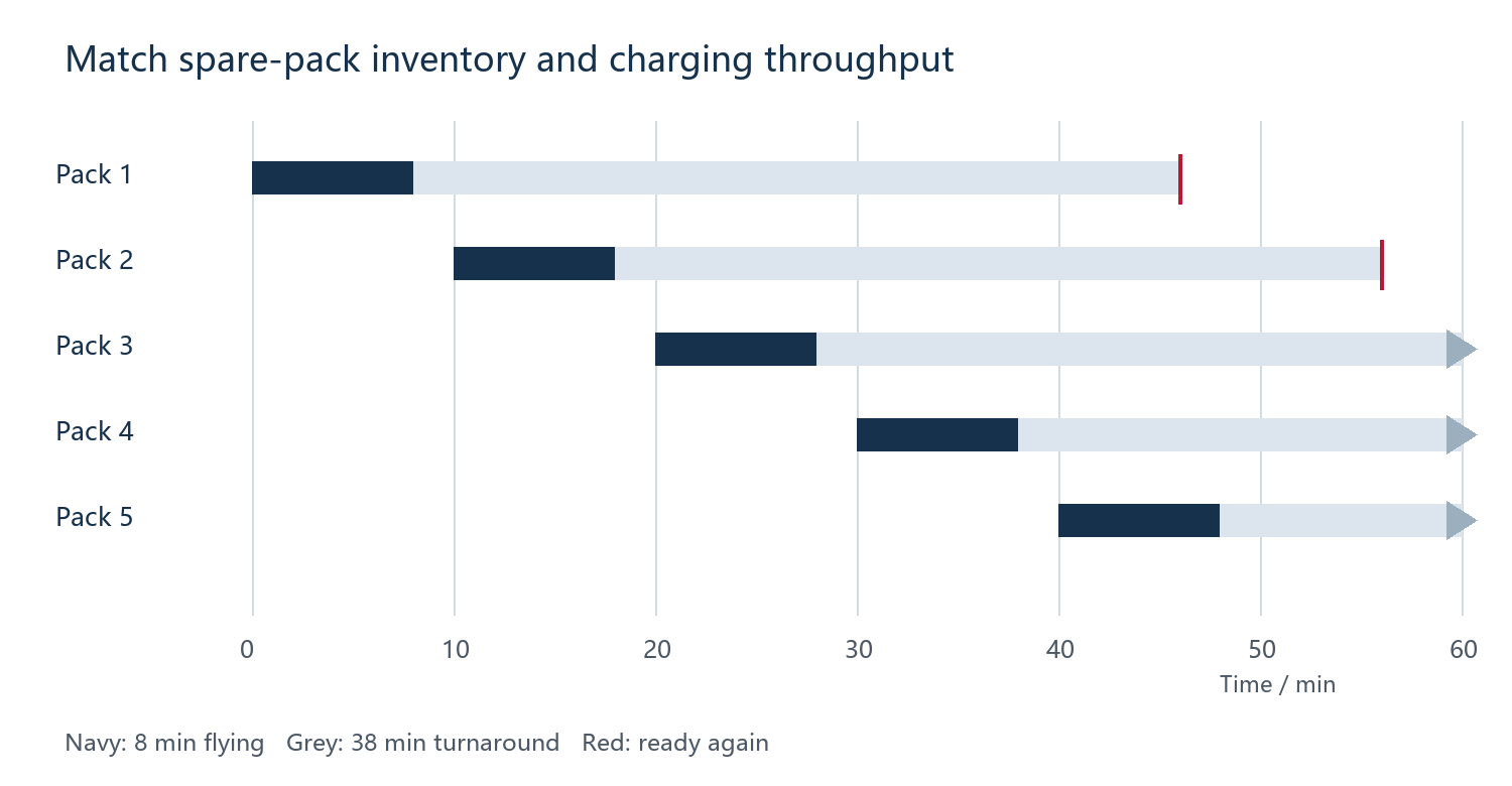
Two channels finish at most two packs per 30 minutes while demand is one per ten minutes. At least three simultaneous channels match the ideal average rate, with additional allowance for delays and shared power. More inventory postpones but cannot eliminate a persistent throughput deficit.
Combine schedules and power budgets for multiple aircraft. Multi-port chargers may share total power; include losses and other site loads. An RFQ should state SOC window, sorties, available power, acceptable waiting and spare-pack budget to compare complete operating costs.
10 Sample testing and acceptance
Freeze configuration and method before testing: inputs, instruments, temperature, SOC, load, logging rate, criteria and owner. Link results to sample serials, cell lots, structure and firmware. A “passed” screenshot does not support repeat procurement.
| Item | Records | Purchasing question |
|---|---|---|
| Receipt/configuration | Revision, condition, size, mass, polarity, accessories | Was the agreed sample delivered? |
| Capacity/energy | Charge/discharge, endpoints, Wh/Ah and temperature | Do claims and budget conditions align? |
| Mission load | V/I, minimum cell voltage, temperatures and alarms | Does any flight phase expose a bottleneck? |
| Turnaround | SOC window, input, time, temperature and queues | Is the sortie schedule achievable? |
| Integration | Restraints, leads, hot joints, vibration and protocol | Are interfaces reliable in repeated use? |
| Repeatability/pilot | Unit variation, repeated missions and causes | Can purchasing scale? |
Replay normal and agreed adverse cases, including a late-mission climb or cold return, rather than only brief full-charge room-temperature discharge. Set sample count by risk, variation and purpose. A few successful samples do not establish zero production defects.
Progress through bench, integration, controlled flight and pilot use. Preserve logs and sample state after anomalies, determine cause and changes, then repeat affected tests. Destructive overcharge, crush or penetration tests require capable facilities and are not introductory customer procedures.
Agree project acceptance values such as late-mission minimum voltage, temperature limits at defined points, charge termination, envelope and permissible variation. Datasheet extremes should not automatically become normal-operation targets. Engineering defines operating limits and margins, then confirms them by testing.
11 Cost per completed mission
Low price need not mean low total cost; high cycle count need not mean low operating cost. Qualify the mission first, then compare battery allocation, charging equipment, inventory, maintenance and downtime per useful mission. A useful mission meets payload, duration and return requirements; laboratory cycles are not a substitute.
Illustratively, A costs USD 420 and completes 240 useful missions: USD 1.75 each for battery purchase alone. B costs USD 600 and completes 500: USD 1.20. If B achieves 300, it becomes USD 2.00 and the ranking reverses. These hypothetical prices and counts illustrate sensitivity, not supplier quotations.
Compare conservative, baseline and favourable outcomes, including extra chargers, power and spares. Retirement must reflect mission performance: capacity alone does not override excessive sag, heat, physical deterioration or connection problems. Agree service scope, exclusions, records, isolation and remedy procedures. Warranty, response times and compensation belong in the contract.
12 Delivery documents and revision control
Separate selection documents, sample/lot validation records and transport/compliance evidence. Similar titles do not establish equal scope. Check model, manufacturer, report number, revision and tested object.
IATA distinguishes lithium-ion/lithium-metal and standalone, packed-with-equipment or contained-in-equipment arrangements. A UN 38.3 summary identifies model, manufacturer, laboratory, report and tests; an SDS is not that summary. An anode-free lithium-metal product is not automatically ordinary lithium-ion because it is rechargeable. Use matching product records and carrier requirements. [R5]
| Milestone | Evidence to agree | Failure prevented |
|---|---|---|
| Quotation | Brief, candidate spec and open issues | Verbal targets replacing limits |
| Sample | Drawing, critical BoM, test plan and revision | Sample differing from quote |
| Production | Sample/pilot results, acceptance and changes | Unvalidated substitutions |
| Shipment | Lot/serial, inspection and transport records | Reports not matching delivery |
| Reorder/service | Consistency, notices and anomaly trace | Untraceable batch variation |
Critical changes include cells/revisions, protection, harness/connectors, structure, charging and firmware. Agree notice, approval and revalidation requirements. Matching photographs do not prove an unchanged version; an existing report does not cover every specification or use.
13 New Journey customization support
Xiamen New Journey Technology Co., Ltd. supports UAV battery customization through technical work on high-energy-cell applications, pack configurations and aircraft interfaces. The useful outcome is a comparable, verifiable, deliverable configuration rather than a capacity recommendation alone.
Start with cell screening, configuration, voltage, output and charging, then define samples around the bay, harness, connectors and communication. Obtain missing aircraft load inputs instead of treating battery specifications as aircraft validation.
| Customer problem | Deliverable to agree with New Journey | Customer/aircraft input |
|---|---|---|
| Insufficient endurance | Energy budget, candidates and samples | Payload/power, reserve and mass |
| Take-off/climb sag | Load analysis, limits and tests | Controller logs, alarms and replay |
| Poor fit/interfaces | Dimensions, restraints, harness/connectors | Bay/interface drawings and integration |
| Charging bottleneck | Charging, spares and channel schedule | Power, sorties and waiting |
| Inconsistent repeat supply | Revision, configuration, acceptance and changes | Approved sample, annex and feedback |
This is a scope to agree per project, not an automatic contract. Confirm model availability, schedule, validation, costs and service after assessment. The battery party owns agreed configuration and records; aircraft engineering owns integration, flight-control strategy and operation. Both agree interface and validation boundaries.
Technical credibility rests on delivery evidence the customer can review: matching specifications, sample records, lot traceability, change control and anomaly handling. Agree which documents each stage requires, who provides them and how they are accepted so selection decisions carry through into supply.
Example project configuration and test records
Use the blank template below to agree the scope of work. It shows a proposed document structure, not a completed customer project or test report. Add the responsible people, revisions and acceptance values for the actual project.
| Record | Required fields | Confirmation |
|---|---|---|
| Configuration | Project ID; full cell model/revision; S/P; mass; drawing; interfaces; protection/firmware | New Journey proposes the battery configuration; customer confirms aircraft interfaces |
| Test | Sample/lot; method; instruments; temperature/SOC; load curve; acceptance values; results and log location | Both agree the plan; the test party enters actual results |
| Change | Old/new revision; reason; affected items; retests; effective lot; approval record | Both agree approval scope and effective conditions |
Prepare the Chapter 14 mission brief to discuss candidate cells, pack configuration and a sample plan with New Journey. The catalogue shows the existing range; custom projects are assessed against the actual mission.
14 RFQ inputs and purchasing checklist
Use the companion customer project brief for an RFQ and attach bay drawings and available load logs. If the model is undecided, start with the mission and hard limits. Assign owners and dates to missing inputs. The blank configuration and test record template below connects the initial discussion to sample approval and reorders.
| Input group | Information required |
|---|---|
| Platform/mission | Configuration, application, payload, phases, sorties and reserve |
| Electrical load | Voltage, sustained/peak current, duration/interval and log location |
| Installation/environment | Bay drawing, mass, restraints, leads/connectors and environment |
| Charging/communication | Charger/input/SOC window, channels, protocol and alarms |
| Purchase/validation | Sample purpose/count, quantity, delivery, tests and acceptance |
| Service/revision | Critical configuration, changes, traceability and service |
Decide each item before sample approval and ordering
First check full voltage, late-mission voltage/energy, current and peak duration, temperature, charged/aged dimensions, interfaces and protection. A hard failure requires rejection or redesign. Then check sample revision, charging throughput, pilot variation, matching documents, acceptance, changes and service. Keep evidence gaps open rather than averaging them away.
Finish with a one-page decision: candidate/revision, reasons it suits the task, rejected alternatives, outstanding tests, sample plan and purchase conditions. Compare endurance, efficiency, total cost and delivery risk only after hard constraints pass.
Appendix Terms and references
| Term | Meaning |
|---|---|
| SOC / SOH / DoD | State of charge / state of health / depth of discharge; identify basis |
| CC/CV | Constant-current / constant-voltage; current tapers in CV |
| S / P | Series / parallel; affects voltage, capacity and current sharing |
| Nominal / usable energy | Nominal V × Ah / delivered energy under defined conditions |
| Sample candidate | Preliminary shortlist awaiting pack and mission validation |
References checked to 25 October 2026. S references are supplied model documents; R references are public primary sources. They support definitions, parameters and methods, not third-party validation of the example aircraft or all New Journey products.
[S1] AEP8390192-49Ah, GF-PS-24032 A2, 2024-11-19, pp. 5–7
[S2] FAP10790192-22Ah, GF-PS-25008 A0, 2025-02-21, pp. 5–6
[S3] FAP105105230-30Ah, GF-PS-24026 A1, 2024-11-11, pp. 5–7
[S4] ECP11087188-39Ah, GF-PS-23016 A2, 2024-11-11, pp. 4–7
[S5] PCP10090192-20Ah, GF-PS-25069 A0, 2025-06-04, pp. 4–7
[S6] PCP104136260-45Ah, GF-PS-25038 A1, 2025-06-03, pp. 4–7
[S7] EBP110105230-50Ah, GF-PS-24071 A3, 2025-08-18; catalogue 2025-09-25
[S8] 86.4V39Ah PACK A0; revision record 2024-09-27, cover 2025-08-25
[S9] Golden Feather product catalogue, 2025-09-25, pp. 1–2; series descriptions
[R1] QuantumScape Battery Technology
[R2] Molicel INR-21700-P45B datasheet, version 1.4
[R3] Texas Instruments TIDA-00449 reference design