 NEW JOURNEY
Agricultural Drone Charging: How Many Batteries and Chargers Do You Need?
Buying more spare drone batteries can hide a charging bottleneck for the first few flights. Once the charged inventory is used, the fleet still has to wait. A useful field plan therefore sizes battery inventory, charging channels and electrical supply together.
This article works through an illustrative agricultural-drone schedule. Its times are planning assumptions, not charge-time claims for a New Journey product. Replace them with measured values from the actual battery, charger, starting state of charge and operating temperature before purchasing the fleet configuration.
Measure the full return-to-ready interval
Start the clock when the aircraft departs. Track flight, inspection, cooling or temperature conditioning, charging and final handling. A pack is available again only when all required steps are complete. Work that genuinely overlaps can be modelled concurrently; a shared person, connector or charging location may turn apparent overlap into waiting time.
A charge C-rate describes current relative to rated capacity. It does not include the entire ground process. Even during charging, current may not remain constant to the endpoint. The lithium-ion section of TI’s Battery Charging application note describes the constant-current/constant-voltage sequence and taper. Use the ordered cell’s actual limits and termination criteria when measuring a cycle.
Work through a five-pack example
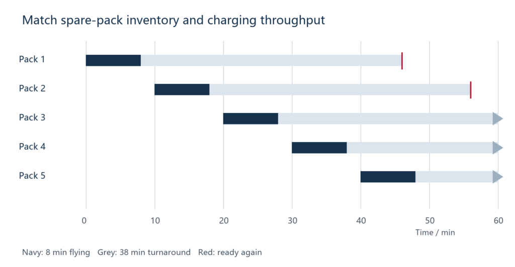
Assume the operation aims for a departure every 10 minutes. Each flight lasts eight minutes. After landing, a pack needs six minutes for inspection and temperature conditioning, 30 minutes occupying a charger channel, and two minutes for final checks and handling.
The first pack departs at minute 0, lands at minute 8, reaches a charger at minute 14, completes charging at minute 44 and becomes ready at minute 46. It is therefore unavailable for departures at minutes 10, 20, 30 and 40.
| Departure | Pack used | Expected ready time after this use |
|---|---|---|
| Minute 0 | A | Minute 46 |
| Minute 10 | B | Minute 56 |
| Minute 20 | C | Minute 66 |
| Minute 30 | D | Minute 76 |
| Minute 40 | E | Minute 86 |
| Minute 50 | A again | Minute 96 |
Five packs cover this ideal schedule because the pack-use cycle is 46 minutes and the departure interval is 10 minutes: ceil(46 / 10) = 5. This count includes the flying pack; it does not mean five additional spare packs per aircraft.
The schedule assumes predictable durations, enough charging channels and adequate shared power. It does not include an additional fault or contingency spare.
Calculate charger throughput separately
Each returning pack occupies a charging channel for 30 minutes. New charging work arrives every 10 minutes. The ideal steady-state minimum is therefore ceil(30 / 10) = 3 independent channels, before allowance for interruptions or delays.
In the example, pack A occupies a channel from minute 14 to 44, B from 24 to 54 and C from 34 to 64. Pack D can begin at minute 44 when A releases its channel. This timing explains why the channel count and battery count are different.
Two channels would not maintain the target indefinitely. Their ideal combined service capacity is four 30-minute charges per hour, while the plan creates demand for six. More precharged packs delay the queue’s effect, but do not correct the throughput deficit.
A charger with several sockets may share a single power limit. Confirm the usable output under simultaneous charging rather than counting sockets as fully independent channels. Repeat the timing calculation using the slower actual charge duration if shared power reduces current.
Check the field power source
Estimate simultaneous output power from the charge voltage and current at the relevant part of the profile. As a separate sizing example, three channels each delivering 50.4 V at 40 A require about 6.05 kW of combined DC output at that operating point. This is an illustration, not a recommended charge setting for the cells discussed elsewhere.
The input supply must cover conversion losses and the other connected loads as well. Use the charger’s specified input requirements and the actual generator or electrical supply capability. Account for the expected ambient conditions and sustained loading. Do not substitute a generator’s short-duration headline rating for the available continuous input supply.
The calculated power is an instantaneous sizing point. Total energy use depends on the charge profile, starting state of charge, efficiency and number of charges. Current taper means that endpoint voltage multiplied by the initial current is not a constant full-cycle energy model.
Test sensitivity before deciding quantities
| Change to the base example | Ideal implication |
|---|---|
| Temperature conditioning rises from 6 to 16 minutes | Use cycle becomes 56 minutes; ceil(56 / 10) requires 6 packs |
| Charge occupancy rises from 30 to 40 minutes | Use cycle becomes 56 minutes and at least 4 charging channels are needed for the same cadence |
| One of 5 packs is removed from service | The remaining 4 cannot sustain the original 46-minute cycle at 10-minute departures |
| Departure interval increases to 12 minutes | The original 46-minute cycle needs 4 packs; 30-minute charges still need 3 ideal channels |
These are arithmetic minimums under the stated assumptions. Choose operational contingency according to the consequences of delay, the variability measured in field trials and the agreed handling procedure. If more than one aircraft shares charging infrastructure, combine their arrival schedule rather than multiplying a single-aircraft result without checking timing.
Connect the schedule to cell and pack selection
The cited FAP22Ah and FAP30Ah cell specifications list a 5C maximum charge rate and a 4.35 V endpoint. Those values make charging capability a relevant discussion, but neither establishes the actual pack’s ready time. The charge configuration, temperature conditions, balancing and termination still have to be agreed and measured. S2, S3
For a 12S configuration at 4.35 V per cell, the full-charge voltage is 52.2 V. Check the aircraft and charger limits before planning around it. A fleet schedule built around an electrically incompatible charging configuration is not a workable purchase plan.
Record a representative operating day
Use pack identifiers to record departure, landing, arrival temperature, charge start, charge end, ready time and any delay reason. Record which charger channel was used and whether its power was shared. That produces a distribution of readiness times instead of one unusually fast demonstration.
New Journey can use those records when discussing capacity, pack quantity, connectors, charger compatibility and the sample programme. The fleet operator should set the sortie target and contingency policy; the battery and charger requirements can then be matched to that target.
Should we solve waiting time by buying more batteries?
First identify the bottleneck. More inventory helps when the battery-use cycle is longer than the available rotation. It does not fix inadequate steady charging throughput or insufficient field power.
Can flight time and charging time simply be divided to find the spare count?
Include the whole departure-to-ready cycle and the actual departure interval. Flight duration alone leaves out inspection, temperature conditioning and handling.
For the complete application scope, see agricultural drone battery solutions. Send the project brief and a sample day log to New Journey before fixing battery and charger quantities.
Specification references
The model values cited above come from the following Golden Feather supplier documents. Use the matching approved revision for the ordered configuration.
- (S2) FAP10790192-22Ah, GF-PS-25008 A0, 2025-02-21, pp. 5–6
- (S3) FAP105105230-30Ah, GF-PS-24026 A1, 2024-11-11, pp. 5–7