 NEW JOURNEY
Heavy-Lift and VTOL UAV Battery Solutions
A heavy-lift multirotor and a fixed-wing VTOL can both require high battery power, but they do not use that power in the same way. A multirotor may sustain lift power throughout the mission. A VTOL may move from a demanding vertical climb into lower-power wing-borne flight, then need substantial power again for landing.
Selecting for peak amperes alone misses the difference. New Journey can support a custom UAV battery project by turning the aircraft’s phase-by-phase duty into a configuration brief covering cell selection, electrical limits, pack structure and interfaces. The useful starting point is a load profile with durations and operating conditions.
Separate sustained lift from transition power
For a cargo multirotor, establish the loaded take-off and hover demand, the cruise or transit load and the return configuration. For a VTOL, identify the vertical climb, transition, cruise, approach and vertical landing phases. Include any required repeat approach in the reserve policy agreed by the aircraft team.
| Mission type or phase | Dominant battery question | Verification focus |
|---|---|---|
| Heavy-lift hover or slow transport | Can the pack support sustained current without excessive voltage drop or heat? | Duration, enclosure airflow, cell spread and connector temperature |
| VTOL climb and transition | Is the permitted high-output duration long enough? | Current versus time, repeated pulses, cooling between events |
| Wing-borne cruise | How much usable energy remains after climb? | Mission energy, reserve and installed mass |
| Late-mission vertical landing | Is sufficient power still available near the reserve boundary? | Loaded minimum cell voltage, temperature and protection behaviour |
These checks prevent a nominally adequate energy store from failing a demanding short phase. They also prevent a high-power design from becoming heavier than necessary for a cruise-dominated mission.
Use the lowest operating voltage for the current check
As an illustrative screening calculation, a 2.2 kW battery-terminal demand at 36 V requires about 61.1 A. If that demand lasts two minutes, a 20Ah 1P candidate rated at a maximum 3C provides a 60 A reference and does not meet the requirement merely because the figures are close.
The cited PCP10090192-20Ah specification also lists a 5C peak for 60 seconds. That peak still does not cover a two-minute demand. The correct next step is to change the candidate or configuration, or revise the mission requirement, then assess the complete pack. Its nominal 3.7 V cell voltage and 4.3 V charging endpoint also belong in the electrical review. S5
Increasing parallel count may change the electrical shortlist, but it changes mass, space, interconnect design and current sharing as well. Do not treat parallel cells as an arithmetic substitute for validating the assembled system. The voltage and discharge-rating guide explains the screening calculations in more detail.
Select the cell family for the actual duty
ECP11087188-39Ah offers one comparison direction: its cited specification lists a 5C maximum discharge rating and a 7C peak for 10 seconds. FAP10790192-22Ah and FAP105105230-30Ah provide another direction, with 10C maximum discharge and a 20C peak for 10 seconds in their cited specifications. S2, S3, S4
These are candidate cell ratings, not interchangeable pack specifications. ECP’s 4.2 V charge endpoint and the FAP cells’ 4.35 V endpoint produce different full-pack voltages at the same series count. Capacity, mass, temperature limits and the intended duration must be considered together.
The higher-output candidate may be worth evaluating for a demanding vertical phase, while another candidate may offer a preferable energy and mass balance for cruise. Establish the conclusion with the intended flight profile; the larger C-rating is not automatically the better procurement choice.
Specify the high-current path and protection behaviour
A pack’s useful output is limited by more than its cells. The specification should cover interconnects and joints, cable size and length, connector contacts, any switching or protection devices, and the mechanical support that keeps these parts stable during operation.
Monitoring, balancing and protection are distinct functions. Texas Instruments’ TIDA-00449 reference design illustrates those functions in a different application; it is useful background for defining requirements, not a ready-made UAV system or a description of New Journey hardware.
For a UAV project, agree the division between battery electronics and aircraft control. Define available measurements, communication protocol and required response to low voltage, overcurrent, overtemperature or lost communication. The aircraft engineer must evaluate those responses in the flight system. A protective shutdown that is appropriate in one product cannot simply be assumed appropriate for every flight phase.
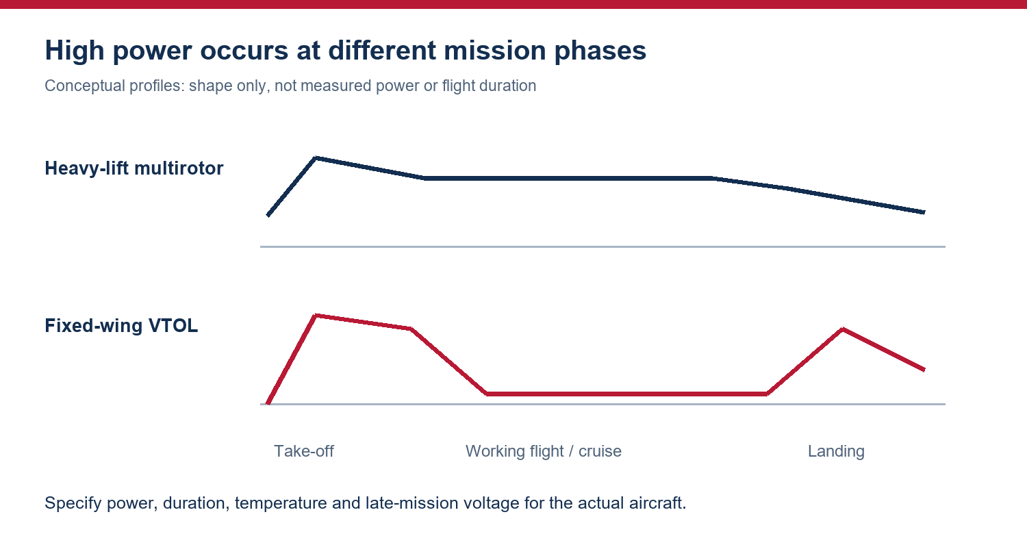
Conceptual mission profiles, not measured aircraft curves. Use the actual power, duration and reserve requirements for the project.
Test a warm pack at the end of the mission
A useful evaluation starts with the agreed initial charge and environmental condition, runs the representative duty, and then applies the required landing or reserve load. Record pack and cell voltage, current, delivered energy, temperature and any protection or communication event.
The thermal measurement plan should cover relevant cells and connection points. Agree sensor positions and criteria before comparing samples; a temperature value without its location and timing can hide the component that determines the operating limit.
Mechanical acceptance should cover pack restraint, centre-of-gravity constraints, connector access and clearance after the specified dimensional changes. Where vibration or environmental exposure is part of the application, define the test method and acceptance criteria with the aircraft team instead of treating an enclosure photograph as proof of suitability.
New Journey customization and purchasing inputs
New Journey can work with the customer on the cell shortlist, voltage and capacity configuration, physical envelope, lead and connector arrangement, protection and communication requirements, and sample documentation. The quotation should identify which design and test outputs are included, which are supplied by the aircraft team, and what constitutes acceptance.
Send a load-versus-time profile, minimum and maximum input voltage, allowable pack mass, battery-bay drawing, connector and communication requirements, operating temperature range and anticipated order quantities. If only a headline power rating is available, identify whether it refers to battery input, propulsion output or a transient limit before using it in calculations.
Can a ten-second peak rating cover a vertical take-off?
Only if the actual event and operating conditions fit the rating, and the assembled pack is verified. A longer climb or repeated event requires the corresponding evidence.
Can New Journey guarantee flight time from a capacity target?
Flight acceptance needs the final aircraft, payload, configuration and mission conditions. A sample project should define those inputs and measure the result rather than derive a flight guarantee from Ah alone.
Use the project brief to discuss a heavy-lift or VTOL battery configuration. The sample acceptance article provides the next-stage test and configuration records.
Specification references
The model values cited above come from the following Golden Feather supplier documents. Use the matching approved revision for the ordered configuration.
- (S2) FAP10790192-22Ah, GF-PS-25008 A0, 2025-02-21, pp. 5–6
- (S3) FAP105105230-30Ah, GF-PS-24026 A1, 2024-11-11, pp. 5–7
- (S4) ECP11087188-39Ah, GF-PS-23016 A2, 2024-11-11, pp. 4–7
- (S5) PCP10090192-20Ah, GF-PS-25069 A0, 2025-06-04, pp. 4–7