 NEW JOURNEY
Designing an Embedded Battery Pack: Space, Wiring and Protection Checklist
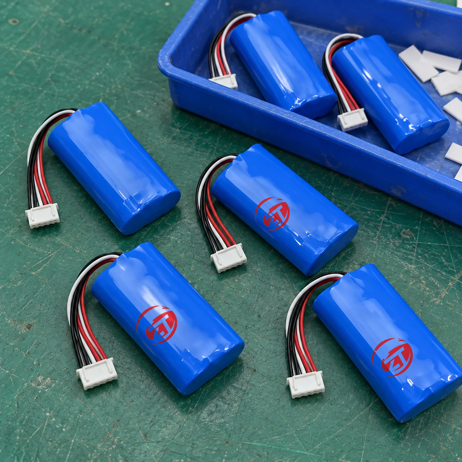
An embedded battery must work inside the final device, not simply fit inside an empty enclosure. Procurement and engineering teams need a shared interface specification before comparing quotations. That specification should connect the available space, operating voltage, load, charging arrangement and mechanical installation to one controlled drawing revision.
This guide explains the information to prepare for a supplier discussion. It does not prescribe a protection circuit or clearances for every product; those decisions depend on the selected cells, electronics and equipment.
Define usable space, not just the enclosure dimensions
Start with a drawing of the actual battery compartment. Identify screw bosses, ribs, moving parts, heat sources and the direction from which the battery is inserted. A rectangular enclosure dimension can hide several unusable areas. State whether dimensions are measured from a prototype or taken from a released drawing.
The battery body is only one part of the installation envelope. Include cable exits, connector engagement and removal, insulation, mounting features and the assembly route. Ask the supplier to identify the measurement basis for its stated dimensions and tolerances. Do not assume that a quoted pack height includes a folded lead or a connector sitting above the pack.
For pouch-cell designs, mechanical handling needs particular attention. The Gens ace handling guide discusses precautions around pouch construction and tabs. Use the actual cell manufacturer’s instructions when deciding how a cell is supported. There is no universal compression percentage or expansion allowance that this article can safely assign to every pouch cell.
Agree the electrical interface as a complete set
Nominal voltage alone is insufficient. Record the device’s allowable input range, shutdown behavior, normal load, startup peaks and charging interface. Clarify whether the device can operate while charging, and which circuit manages that operating state.
| Interface item | Buyer should provide | Supplier should confirm |
|---|---|---|
| Input range | Device minimum and maximum voltage | Pack voltage range for the proposed design |
| Operating load | Typical current and duty cycle | Applicable continuous discharge limit and conditions |
| Transient load | Peak current, duration and repetition | Whether the proposed configuration supports that profile |
| Charger | Output behavior and intended connection | Compatibility with the exact pack charging requirements |
| Cable assembly | Length, routing and connector location | Wire, connector and pinout definition |
| Additional signals | Temperature, identification or communication needs | Supported signal behavior and interface documentation |
Treat unanswered rows as open engineering items. A connector with the correct physical shape is not proof of matching polarity, current capability or signal assignment.
Clarify what protection actually does
Ask which functions belong to the pack and which remain in the device or charger. Relevant topics can include overvoltage, undervoltage, overcurrent, temperature monitoring and balancing, depending on the design. Do not assume that every battery contains the same protection functions or that a protection cutoff is a normal operating control.
Texas Instruments’ BQ76952 documentation illustrates how configurable monitoring and protection can be in multi-cell designs. It is a component reference, not evidence that this component is installed in a New Journey product. The supplier’s schematic-level review, configuration record and test evidence must describe the actual offered pack.
Check the installation and service sequence
Review the assembly route with the people who build and service the equipment. Can the harness be connected without tension? Can a technician disconnect it without pulling the wires? Could a screw, sharp edge or repeated movement contact the battery? Is a replacement pack mechanically prevented from being installed incorrectly?
Evaluate temperature in the installed device under a defined load and ambient condition. A room-temperature bench test outside the enclosure does not establish the thermal behavior of the finished equipment. Agree where temperature is measured and what constitutes an acceptable result before testing begins.
Use one controlled handover sheet
The quotation, sample label, drawing, wiring definition and acceptance checklist should refer to the same revision. Record who approves changes to cells, protection settings, insulation, cable length and connectors. A visually similar substitution can affect the device interface.
A useful handover sheet has four states: confirmed, proposed, awaiting buyer input and awaiting supplier evidence. Assign an owner and due date to every unresolved item. This makes a quotation more actionable than a list of optional features with no agreed configuration.
Discuss a relevant starting point
The 7.4V 5000mAh pack and 3.7V 1500mAh LiPo battery are catalogue references for different device discussions. Neither should be assumed to fit an enclosure without checking its current specification. Browse embedded battery packs and send your compartment drawing and load requirements when requesting a configuration review.
Questions buyers often ask
Can the battery be selected before the enclosure is finalized?
Yes, as a coordinated design exercise. Keep the battery envelope and electrical requirements under revision control so neither team silently changes the interface.
Is a protection board enough to make any charger compatible?
No. The charger must meet the exact battery’s charging requirements. Protection functions do not replace a compatible charging system.
Which drawing should accompany an inquiry?
Send the battery compartment, mounting arrangement and cable/connector location together, with units and revision. Include the electrical requirements in the same inquiry.
Explore battery selection resources · Discuss your configuration