 NEW JOURNEY
Long-Endurance Drone Battery Solutions for Inspection and Mapping
An inspection aircraft may finish its outbound survey with energy still in the battery and yet struggle to return against the wind. A mapping platform may gain capacity but lose useful payload because the replacement pack is heavier. Both problems begin when battery selection is reduced to an amp-hour number.
For long-endurance inspection and mapping, New Journey helps customers define a battery configuration around the mission, the aircraft’s electrical limits and the available mass and installation space. The first decision is whether the project needs more survey time, more payload or lower take-off mass. These are different design targets; one battery change does not automatically deliver all three.
Define what a successful mission looks like
Start with the work the aircraft must finish: a corridor length, a mapping area or a sequence of inspection points. Record payload, altitude profile, expected temperature and the operator’s return reserve. Separate take-off, climb, transit, measurement, return and landing. Use battery-terminal power measurements where available, so propulsion losses are not deducted twice.
Mapping with a steady forward flight profile differs from inspection that repeatedly hovers, changes height and pauses near structures. Even if the two missions use the same aircraft, average power and the time spent at high load can differ. The useful comparison is energy delivered through the intended mission while retaining an agreed reserve.
| Project priority | Battery design question | Evidence to collect |
|---|---|---|
| Longer survey time with the same payload | How much usable energy can fit within the installed mass limit? | Phase power log, usable energy at operating temperature, pack mass |
| Carrying a heavier sensor | Can battery mass fall while the original mission remains achievable? | Payload and balance limits, revised power profile, return reserve |
| Fitting an existing airframe | Can cells, structure and wiring fit throughout the specified operating life? | Battery-bay drawing, connector access, cell dimensional conditions |
| Repeating remote missions | Can the fleet recharge, transport and rotate packs reliably? | Charger availability, readiness time, identification and maintenance records |
Choose an energy-focused cell without losing output capability
A high-specific-energy cell is useful when cell mass constrains stored energy. It still has to supply the take-off and manoeuvre current at the relevant temperature and state of charge. Two candidate cell families illustrate why this check changes a shortlist.
The Golden Feather AEP8390192-49Ah specification lists 3.8 V nominal voltage, 49 Ah capacity and 390 ±5 g cell mass. Its maximum discharge rating is 1C at 0–45°C; the −20–0°C range is limited to at most 0.3C. A 1P configuration therefore has a very different current envelope from a higher-output cell, despite its larger capacity. S1
ECP11087188-39Ah lists 3.6 V, 39 Ah and 430 ±5 g, with a 5C maximum discharge rating and a 7C peak for 10 seconds. Those numbers make it a candidate to discuss where output is more demanding. They do not establish that an assembled pack can sustain the same current across its whole temperature range. Interconnects, protection, cable, connector and cooling must be specified together. S4
For either direction, compare the relevant discharge curves and the complete mission, rather than choosing from a density headline. The companion cell energy-density article explains how to compare cell-level values without confusing them with installed-pack measurements.
Connect the shortlist to the aircraft mass budget
Consider a screening example with a 7.0 kg installed-pack limit. Twelve ECP39Ah cells have a nominal combined mass of 5.160 kg. Including the stated ±5 g tolerance per cell gives 5.100–5.220 kg, leaving at most 1.780 kg for interconnects, insulation, restraint, wiring and any electronics at the upper cell-mass limit. That is a design allowance to verify, not a measured pack mass.
Twelve PCP104136260-45Ah cells, at 764 ±5 g each, would total 9.108–9.228 kg before those additional components. This particular 12S1P configuration fails the example’s 7 kg limit even though it may remain relevant to a platform with a larger mass allowance. This comparison does not recalculate or challenge either cell’s energy density. S4, S6
After selecting a physical configuration, measure the sample mass and update the aircraft power budget. Keeping the original flight power assumption while changing battery mass can produce an attractive but unusable endurance prediction.
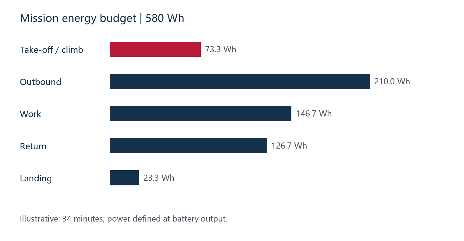
Illustrative planning example: 580 Wh over a defined 34-minute duty. It is not a flight result or a promised endurance figure.
Validate the return and landing conditions
A sample evaluation should include the end of the mission, when the aircraft may still need climbing or landing power. Record pack voltage, the lowest cell voltage, current and temperature under that load. An energy total alone will not reveal a protection trip or an unacceptable voltage drop.
Installation review also needs the cell’s dimensional measurement conditions. For ECP39Ah, the specification gives an initial thickness limit of 11 mm under a 2000 gf PPG measurement condition and a 13.2 mm limit after the cycles defined in section 6.1.2. A tray designed only around the initial number may not represent the required lifetime envelope. Add the actual pack restraint, insulation, lead exits and service access to the drawing. S4
What New Journey can help specify
New Journey’s customization work can support the move from a cell shortlist to an agreed battery configuration: series and parallel arrangement, capacity target, pack dimensions, lead length and connector, protection and communication requirements, and a sample evaluation plan. Select the deliverables required for the project before ordering samples; the aircraft team retains responsibility for airframe integration and flight acceptance.
A useful first enquiry includes the mission profile, allowed voltage window, highest sustained load with its duration, peak events, installed mass limit and battery-bay drawing. Include the existing charger details if it must be retained. These inputs let the discussion address a feasible configuration rather than a capacity-only replacement.
Questions buyers often ask
Will a larger-capacity battery always fly longer?
No. It may add usable energy, but mass, output limits and aircraft power also change. Evaluate the revised installed configuration at the intended payload and return reserve.
Can we keep the same connector and charging equipment?
Sometimes, but matching the plug shape is insufficient. Confirm pin assignment, polarity, current and temperature limits, full-charge voltage and any communication requirements.
Can these cells be ordered as an existing website pack?
Use the cell model and specification revision as a starting point for a custom enquiry. A finished pack must have its own confirmed configuration, specifications and document scope.
Send your operating profile using the UAV project brief, or discuss an inspection or mapping battery project with New Journey. Existing pack references are available in the drone battery catalogue.
Specification references
The model values cited above come from the following Golden Feather supplier documents. Use the matching approved revision for the ordered configuration.
- (S1) AEP8390192-49Ah, GF-PS-24032 A2, 2024-11-19, pp. 5–7
- (S4) ECP11087188-39Ah, GF-PS-23016 A2, 2024-11-11, pp. 4–7
- (S6) PCP104136260-45Ah, GF-PS-25038 A1, 2025-06-03, pp. 4–7