 NEW JOURNEY
3.7V, 7.4V and 11.1V Battery Packs: Matching Your Device’s Input Range
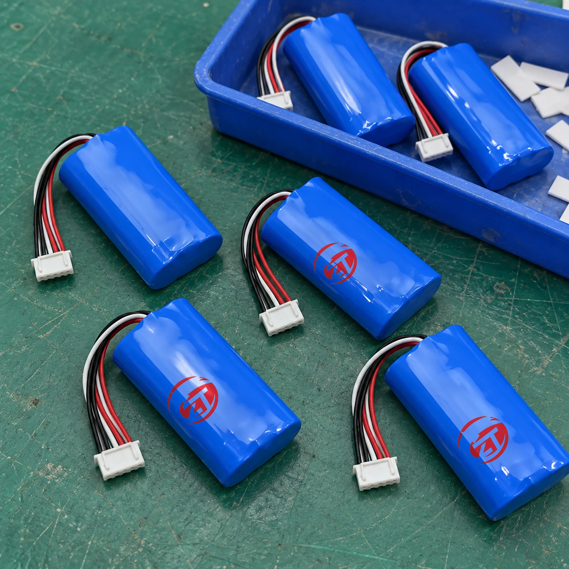
A battery’s nominal voltage is a naming and comparison value, not a constant regulated output. Equipment sees a changing voltage during charging and discharge, with further variation under load. Selecting an embedded pack therefore starts with the device’s permitted input range and its charging design, rather than matching a number printed on the enclosure.
Understand nominal and maximum voltage separately
For an illustrative cell family rated at 3.7 V nominal and 4.2 V maximum charge voltage, series connection gives the values below. These assumptions are stated to explain the relationship; they do not apply to every lithium chemistry or every product using a similar marketing label.
| Illustrative arrangement | Nominal voltage | Maximum charge voltage under the stated assumption | What still needs checking |
|---|---|---|---|
| 1S | 3.7 V | 4.2 V | Cell specification and device input limits |
| 2S | 7.4 V | 8.4 V | Charger, protection and balancing requirements |
| 3S | 11.1 V | 12.6 V | Full device operating range and load response |
The lower operating limit must come from the approved cell and pack specification, considered together with the equipment’s requirements. Do not derive it from the nominal value. A different cell chemistry or charge-voltage variant requires a different assessment.
Check both ends of the device’s input range
At the upper end, confirm that the device can tolerate the battery’s maximum permitted voltage, including the intended charging arrangement. At the lower end, determine when the device can no longer operate normally. The battery’s protective cutoff is not necessarily the correct point for the device to stop working.
Also check startup and pulsed loads. A motor, radio transmitter or other intermittent load can create a brief voltage drop that does not appear in a simple average-current calculation. Ask for operating and startup current information, then review the selected pack under the relevant conditions.
Keep the charger, protection and regulation functions distinct
A charger controls how energy is put into the battery. Protection circuitry enforces specified boundaries or interrupts abnormal conditions. A regulator or converter provides a controlled supply to the device when that function is required. Having one of these functions does not prove that the others are present.
TI’s BQ2057C charger documentation identifies a 4.2 V single-cell charge controller; the wider BQ2057 family includes other charge-voltage variants. The purchasing lesson is to identify the exact charger configuration rather than assume one circuit is suitable for all lithium packs. The document does not identify the charging hardware in New Journey products.
For general background, TI’s battery charging application note explains constant-current and constant-voltage charging behaviour. Its example settings are not universal instructions; the selected battery’s current specification and charger documentation govern the project.
Build a device-to-battery compatibility record
Prepare a one-page record containing the device input limits, normal current, startup or peak demand, available battery space, connector and polarity, charging method, temperature range and expected operating time. State whether the battery remains inside the device while charging and whether the device operates at the same time.
If a DC converter is needed, account for its efficiency and its own input range. Capacity measured on the battery side should not be confused with capacity at a converted output voltage. Compare energy when estimating runtime, and label any efficiency assumption clearly.
Compare samples using the final enclosure
A pack that works on an open bench may behave differently in a confined housing with nearby heat sources. Review the complete installed envelope, retention and cable route. Agree temperature measurement locations and the intended load sequence before evaluation.
Keep a record of the approved charger and device firmware as well as the pack revision. If the customer’s device changes its startup behaviour, the earlier battery approval may need review even when nominal voltage and capacity remain unchanged. The same applies to substitutions in the cell, connector or protection configuration.
New Journey’s 3.7V 2600mAh, 7.4V 5000mAh and 11.1V 6000mAh catalogue entries illustrate different voltage groups. Review the Embedded Battery Packs category and provide your device input limits before selecting a model.
Buyer question: Can an 11.1 V battery replace a 12 V power adapter?
Not on nominal voltage alone. A regulated adapter and a battery have different output behaviour. Check the battery’s full operating range against the equipment’s limits and determine whether an appropriate converter is required.
Explore battery selection resources · Discuss your configuration